DISCLAIMER! Lithium-ion batteries are dangerous and can even explode under certain conditions, such as overcharge, short circuit, etc. Avoid overcharge, overdischarge, overcurrent, short circuits, overheat and mechanical damage.
I bought this power bank kit for around 30 CZK (around 1.2 USD) on Ebay. It seems to be decently built and works fairly well for such a low price. It takes regular rechargeable unprotected 18650 lithium-ion batteries (3.6 or 3.7 volt nominal voltage). These are quite commonly used in laptop battery packs, etc.
The kit consists of an aluminium body with an unscrewable back end and a plastic battery holder, which also holds the electronics (a small circuit board with only a few parts). It can be assembled by inserting an 18650 battery into the battery holder, putting the battery holder inside the casing and screwing the back end on. This should not take more than a few seconds.
My only complaint about the mechanical quality is that the plastic holder seems to move inside the aluminium body a bit, but that can be fixed by putting a piece of foam and tape inside the back end. The black paint can also be stratched off, but it's not that easy.
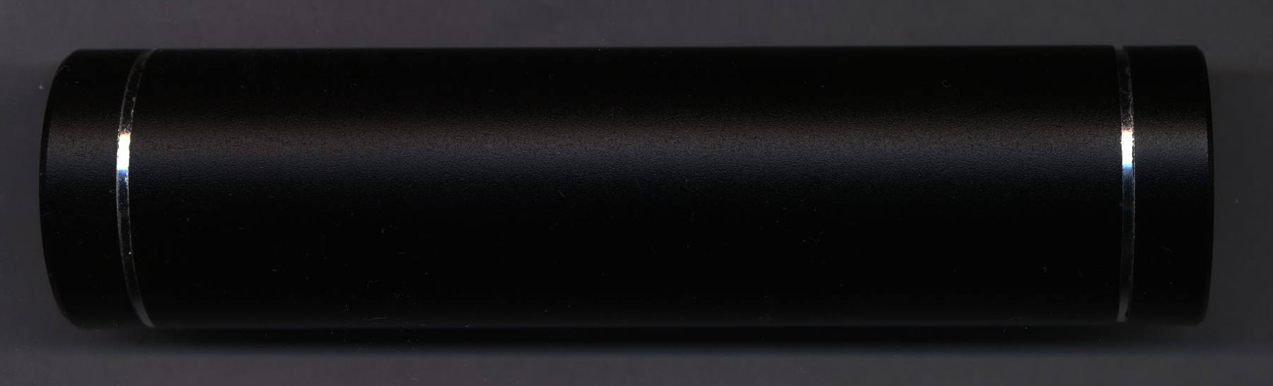
The kit from the outside (click for full resolution)

Electronics + holder with a battery inserted (LG S3 18650 3.6V 2.2Ah) (click for full resolution)

Electronics (top side) (click for full resolution)

Electronics (bottom side) (click for full resolution)
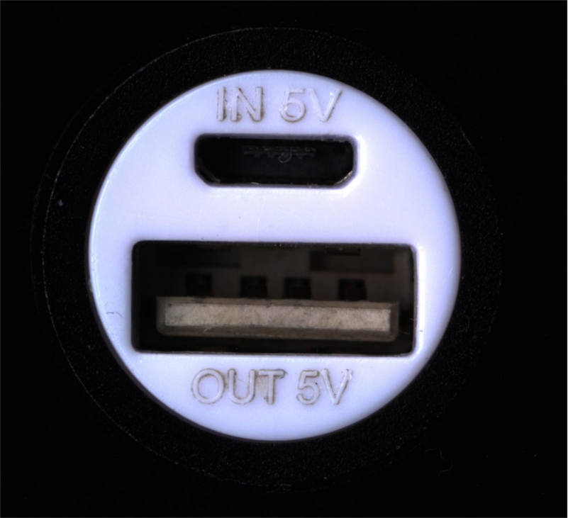
Front connectors (click for full resolution)

Reverse engineered schematic (click for full resolution)
The little circuit board is based on the MP3401A chip. I haven't managed to find an English datasheet for this chip (manufactured by TPS - TK Plus Semi - some Chinese company), so I had to use the Chinese one with some help from Google Translate. There also are 2 capacitors, 2 LEDs, a Micro USB connector, a regular USB connector and a 1.5µH inductor.
The MP3401A chip takes care of all the necessary function of the power bank - charging, protection and voltage boosting. It integrates a CCCV linear battery charger, with typical charging current of 0.7A (the value I measured was slightly higher, but close) with charge termination at 1/10 charging current (70 mA). Mine seems to switch from CC to CV mode at about 4.15 volts, which is OK. It is slightly under the rated maximum voltage for regular Li-Ion cells. It should also charge at a low current when the battery voltage is under 2.9V. The chip also integrates protection circuitry, which should turn the power bank off if the battery gets discharged below 2.9V and has some hysteresis (which could be bigger though, doesn't work that well with old cells). It also should protect against overload, overheat and short circuits. The integrated synchronous boost converter boosts the battery voltage from 2.9-4.2 volts to 5 volts (nominal USB voltage) and should be able to supply up to 1A (tested and works fine - note: tested after soldering that decoupling capacitor (mentioned later) in place).
The boost converter doesn't run continuously when there's no load. When an AM radio tuned to the right frequency is put close to the powerbank, a clicking sound with intervals somewhere around 1/4 sec. can be heard, as the voltage booster attempts to start, but soon shuts down when there's no load, it runs just in short bursts to keep the output voltage at the filtering capacitor at around 5.1V. When the load increases, the interval decreases, the sound from the radio receiver changes into a buzzing sound and eventually into a continuous hiss. Under a short circuit or overload condition, the power bank goes into that "burst mode" again, but the interval is a bit longer. When the fault condition is removed, it goes back to normal working mode after a few hundred milliseconds.
There are 2 indicator LEDs - a red one and a blue one. The blue one lights up when a load above approximately 20 mA is connected and starts blinking when the battery gets low. The red one indicates charging (blinking when charging, continuously lit when charged). The quiescent current draw with no LEDs lit is about 110 µA. This is OK, but could be better.
The MP3401A chip heats up quite a lot. What is very bad though is that there is NO decoupling capacitor on the battery input (!!!), although there's a place for it on the PCB. It works OK, but the ripple may be quite high. I soldered a 10uF 0805 MLCC capacitor in that place. The output capacitor also seems quite small. But that was expected, considering the fact that it operates at around 1 MHz.
This seems to be an OK product. It works, but there are a few non-idealities (e.g. missing decoupling cap (quite a big design fault), no external protection - everything is relying on the MP3401A's integrated protection. But actually I think it's fairly decent, considering the low price.
Here is the Ebay link, if you want to buy it.