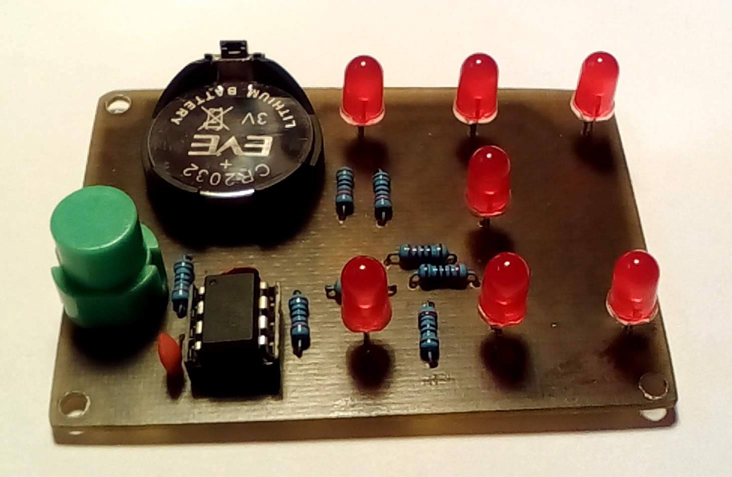
Assembled circuit board (click for full resolution)

Circuit diagram (click for full resolution)
This is a simple electronic dice based on the ATtiny13 microcontroller.
A single momentary button switch is used for control. Pressing the button turns on the electronic dice, as long as the button is pressed, all LEDs stay lit. The pattern (1-6) is displayed after releasing the button. Pressing the button again either turns off the dice (if pressed for 20-400 ms) or "rolls" the dice again (if pressed for >400 ms). The device also automatically turns off when unused for >20 seconds.
The microcontroller used here has a mode called "power-down" mode where the current draw is <1 µA (with a 200 mAh battery, it would last ~20 years in this mode). In this mode the microcontroller shuts down the clock source (oscillator), but the register contents remain and it can be woken up by an external interrupt (this is done using the button). The code is written in assembly.
All 5 available I/O pins are used: 1 input (with internal pullup - button) and 4 outputs - there are 3 pairs of 2 LEDs and one individually controlled LED (center). There's a 220 Ω resistor in series with each LED, maybe it would be better to choose a higher value (~1 kΩ) as the current draw is quite high (for the CR2032 cell) with 220 Ω resistors.
The fuse settings are: HFUSE=0xFF, LFUSE=0x7F (128 kHz internal oscillator, no Brown-out detection).
Here is a video of the dice in operation.
ZIP archive - assembly source code, HEX file, circuit board pattern for toner or photo transfer (600 DPI PNG file).