WARNING! Dangerous voltages are present in this device. Even though the power supply has low output current, be careful. If you decide to build this device, you do so at your own risk.

Circuit diagram (click for full resolution)
The circuit diagram is taken from Linear Technology's application note AN-72. Instead of a special avalanche transistor, 2N3904 was used due to its availability. It works relatively well in this mode, but isn't designed for it, so it might be necessary to test a few pieces before finding one that works adequately.
The principle of operation is simile. The generator is powered from a 180 V source. Capacitor C1 is charged through resistor R1, until the voltage reaches around 120 V. After this, the transistor breaks down and quickly discharges the capacitor into the load. The energy is fairly low, the breakdown should not be destructive. Avalanche breakdown is very fast. This design has a 50 Ohm BNC connector on the output.

Circuit diagram (click for full resolution)
This is a self-oscillating flyback converter. The output voltage is 180 V. It is able to supply around 1-2 mA at this voltage.
T1 is a small transformer made out of a base drive transfomer from an old ATX supply. The middle section has an area of approximately 25 mm2. A small air gap is added. The secondary coil (120 turns) has an inductance of around 1 mH.
The circuit is started through R1. Feedback is done using an auxiliary winding (7 turns), coupled to the base of Q2 through R4, C3. It operates in self-oscillating mode. When Q2 starts turning on, it gets fully turned on by feedback from the auxiliary winding. Current through the primary rises. When the current reaches a certain value (enough to cause a ~0.6-0.7 V drop across R2, R3), Q2 starts turning off and gets fully turned off by the feedback. Energy stored (magnetically) in the transformer "gets out", causing voltage reversal on all windings. The resulting pulse on the secondary coil is rectified by D4. The output filtering capacitance can be fairly small (470 nF). Current limit is set using R2, R3, D2, D3. Diodes D2-D3 prevent the voltage between base of Q2 and GND reaching over 1.2 to 1.4 V. The transistor starts to turn off when the voltage across R2, R3 goes over approximately 0.6 to 0.7 V - base-emitter voltage will drop below the necessary voltage (0.6 to 0.7 volts at room temperature at normal current). This is not very accurate, but works well enough for crude current limiting - peak current is limited to ~300 mA. The output voltage is limited by D5 and Q1 (when enough current starts flowing through D5, the voltage drop across R5 and C4 will be large enough for Q1 to start conducting - this will prevent Q2 from turning on by clamping its base to GND).

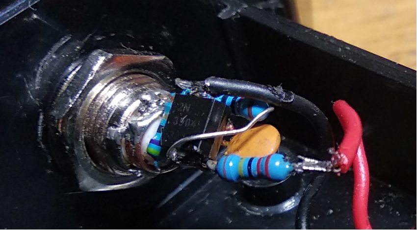
Inside (click for full resolution)
The power supply was constructed on a piece of protoboard, the generator was constructed in air (and later rebuilt for lower stray inductances - this layout isn't optimal). Rise time is somewhere around ≤1 ns.

Oscilloscope (click for full resolution)
You can see the output displayed on a Hantek DSO5102P oscilloscope (rated bandwidth 100 MHz). The bandwidth can be estimated from measured rising edge time (if we assume a single pole response at high frequencies):
Modified pulse generator circuit (click for full resolution)
Modification - February 2021: wires in the pulse generator circuit were shortened. A 0,5 A fuse was also added (in series with the power switch).