DISCLAIMER! High voltage experiments are dangerous. I refuse to take ANY responsibility for any possible injuries, legal problems, property damage or deaths, anything you find here is provided WITHOUT ANY WARRANTY and you do everything AT YOUR VERY OWN RISK!

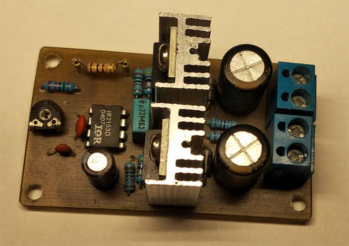
Populated circuit board (click for full resolution)
This is a small high voltage transformer driver with a half bridge topology based on the IR2153 integrated circuit (it can be used for different things as well). The output is a square wave. There are many similar ICs that can also be used (IR2153D, IRS2153D, IRS21531D, L6571 etc. - maybe even TS19706 or GR8853 with an external Zener clamp). This IC (IR2153) is a MOSFET driver which contains an oscillator, under-voltage lockout, deadtime circuitry and a Zener diode.

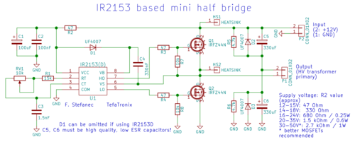
Circuit diagram (click for full resolution)
P2 is used for power input. I used classic 5 mm terminal block connectors. Capacitors C5, C6 (approximately 330 µF - should be low ESR, high quality capacitors rated for at least the input voltage) are used for filtering and as a voltage divider. It's a good idea to connect some 1 µF ceramic or foil capacitors parallel to them. Resistors R5, R6 (4,7 kΩ) and diodes D2, D3 are also connected parallel to the capacitors.
The IR2153 IC is powered through the resistor R2. Capacitors C1, C2 are used for filtering. This IC has a built in Zener diode connected in parallel with Vcc/COM, which will clamp the voltage to approximately 15 V. There's a table with suitable input voltages/R2 values included in the schematic diagram.
The operating frequency is approximately 20 to 30 kHz and is determined by C3, RV1 and R3 (1,5 nF, 10 kΩ, 15 kΩ). It can be adjusted using RV1. The range can be changed by changing the values of those 3 parts, but it's not good to exceed 50 kHz due to the fairly high deadtime and low drive current.
The upper MOSFET driver is powered through D1 (can be omitted if using IR2153D), C4 (should be a low ESR/ESL capacitor - film or ceramic). Resistors R3, R4 (47 Ω - between the driver and the MOSFETs), R7, R8 (10 kΩ between the gates and sources of the MOSFETs).
Some heatsinking is needed or at least recommended, the MOSFETs are placed on small heatsink, depending on the load and MOSFET type, the MOSFETs might heat up. I'm afraid the IRFZ44Ns I used here are fakes (due to somewhat higher Rds - higher Rds will result in more heating) and I will replace them later. I used small heatsinks from AliExpress (21x15x10 mm). Required heatsinking will vary with your setup.
P1 is another terminal block connector. It's the output of this circuit. I used a small unrectified high voltage transformer from a plasma ball. I wound 5 turns of fairly thick wire (there's plenty of current) on the exposed part of its core.
The IR2153 integrated circuit can be used in other applications as well - fluorescent ballasts, power supplies or mains-powered high voltage transformer drivers (see Danyk's website for example).
KiCad 4 files (schematic, PCB layout) can be downloaded here.