The Hantek DSO5102P is a relatively low-end digital storage oscilloscope sold for approximately 250 US dollars.

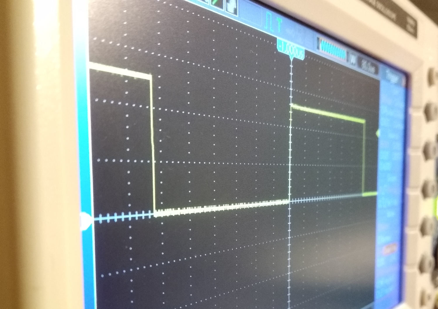
Oscilloscope (click for full resolution)
The build quality is reasonable - the plastic chassis doesn't feel flimsy. There's a 7 inch LCD display, push buttons, rotary encoders, USB host port, BNC connectors, a square wave output (for probe compensation) and a power button on the front panel. The horizontal viewing angle of the LCD display is good, the vertical viewing angle is somewhat worse. The front-panel buttons are membrane type. Some of them are translucent with light indication of current state - they are underlit with LEDs, but some of them are unpleasantly bright. The bigger rotary encoders (volts/division, seconds/division) are not clickable. They have a fairly good feel. The smaller encoders are pushable (push resets original value), but don't feel as good - not much feelable feedback when rotating. The oscilloscope has two rubberized feet at the back + two foldable non-rubberized feet under the front panel - it is possible to slightly tilt the oscilloscope for more comfortable use. There is a cooling fan on the side. There's a classic IEC power connector and USB-B connector on the rear.
Horizontal view (click for full resolution)

Vertical view (click for full resolution)
The encoders and buttons are well laid out. I personally like the separate volts/div & position controls for the inputs - this is a feature I personally miss on some other low end oscilloscopes. There are some inconsistencies/bugs in the user interface, although I haven't found any really major issues. Overall I find it to be quite pleasant. The speed is OK, but there is some noticeable lag which becomes somewhat uncomfortable as long as more demanding features (for example FFT) are enabled, or if many features are enabled at once. One of the most annoying bugs I found is that the Measure function doesn't seem to work properly after stopping acquisition, setting different time base and trying to use the Measure function again on the data in memory. I have also experienced a lock up/reset after playing with many features at once, however this doesn't seem to happen often. All user interface screenshots were taken using the "Save to USB" button.
The 40 kpts sample memory is fairly low and might become a problem when long waveforms/many points need to be recorded (e.g. modulated signals). The oscilloscope is capable of working in X-Y mode, but only at 1 Msps. The analog front end and ADCs are a bit noisy, but it's not a big problem (personally, I found many other low end oscilloscopes such as the Rigol DS1052E to be "noisier").

GUI (click for full resolution)

GUI (click for full resolution)

GUI (click for full resolution)

GUI (click for full resolution)
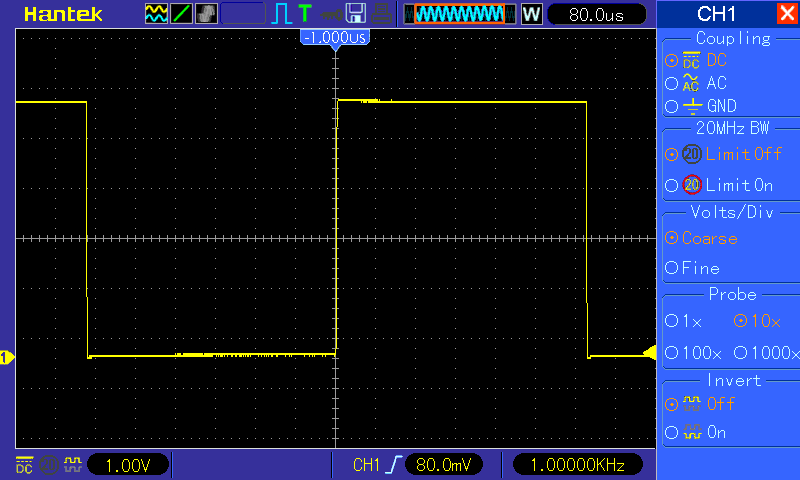
GUI (click for full resolution)
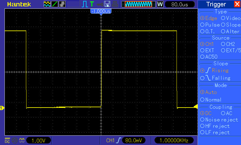
GUI (click for full resolution)
The oscilloscope is based on a Samsung SoC (S3C2440 or similar) running Linux. There is also an FPGA (probably Altera Cyclone III). 4 dual ADCs are used (Analog Devices AD9288, possibly cheaper equivalents). They are overclocked to 125 MHz and running in interleaved mode to get 1 Gsps or 2x 500 Msps. The analog circuitry seems to really have 100 MHz bandwidth (measured 3.25 to 3.3 nanosecond rise time with an avalanche pulse generator, which corresponds to approximately 350/3.275=107 MHz). Actually it is software-limited and can handle 200+ MHz . There are two circuit boards - the main board containing the SOC, FPGA, ADCs... and a power supply board, which seems to be of reasonable quality, but of course the capacitors come from fairly unknown brands - which is to be expected at this price point. There is also a 50 mm cooling fan inside the oscilloscope.

Main board (click for full resolution)
You will probably lose warranty by modifying the oscilloscope. There is a risk of damaging the oscilloscope. There is mains voltage present in the power supply - risk of electric shock. You do everything at your own risk. I refuse to take any resposibility for any consequences. The following text is provided without any warranty.
Second warning - I tried this unlock on a friend's oscilloscope and after the EEPROM modification, it ended up in recovery mode. After recovery, I had problems with self-calibration failing, and the serial number disappeared. The problem was fixed by repeating the steps with copying the modified EEPROM files to the oscilloscope's root directory - I copied the same file to both i2c.org, i2c.log and created the format file. After a reboot, it worked correctly and it was possible to run self-calibration normally and all settings were normal. This unlock method may not be reliable, you perform it only at your VERY OWN RISK!!! I used the newest available firmware.
I bought this oscilloscope in early 2019. Older models could be unlocked much more easily.
There is an unpopulated place for an UART header (pinout marked in the main board photo). 3.3 volt levels are used. I used a CH340G-based USB to UART adapter (connecting GND to GND, adapter TX to scope RX, adapter RX to scope TX) with Minicom running on a Linux Mint PC as the serial terminal. The baud rate is 115200, standard 8-N-1 data format.
After the oscilloscope finishes booting, pressing Enter inside the terminal allows command line root access to the Linux system running on the SoC.
To stop the DSO application, run the following command: killall dsod
The older models could be simply unlocked by renaming "dso5102p" to "dso1202p" and editing some other text files (changing strings "5102P" to "5202P", "1102B" to "1202B") - sys.ini, logotype, logotype.dis. Only the vi editor is present. To change a character, move cursor with arrow keys, press r to rewrite, Esc followed by :wq Enter to save and exit - or Esc followed by w! Enter to exit without save).
mv dso1102b dso1202b
vi sys.ini
vi logotype
vi logotype.dis
However, this doesn't seem to work on newer models - the files revert to original state after reboot. To make this work, the EEPROM needs to be edited (warning: proceed carefully, I got the oscilloscope stuck in a reboot-recovery loop by accidentally deleting a character in the EEPROM file, which I eventually solved by killing the dsod process when it was attempting to update the EEPROM again after a FLASH recovery/factory reset attempt and redoing the process from here with the correct file format, but please be careful and don't brick the oscilloscope!)
I attached an USB flash drive (tested to work with the scope before) and copied i2c.log (containing EEPROM contents) on there.
cp i2c.log /mnt/udisk/i2c.log
sync
I then removed the flash drive, connected it to the PC, backed up the file. It contains some extra garbage, which I removed with Bless Hex Editor and opened the file with Xed (using Unix line ending when editing/saving). Not removing it led to the scope failing to self-calibrate. Windows users might need to find some alternatives. After opening the cleaned up file, change line "[bw]200" to [bw]100". Don't change other lines. (If there is no such line, skip the entire EEPROM editing process or modifications/copying of any i2c.* files and just reboot the oscilloscope). The edited file should look like this:
[--LOG0--]
[serial number](YOUR ORIGINAL SERIAL NUMBER)
[operation time]2018-10-29 10:37:05
[operator]hantek
[pcb]101
[lcd]3
[front]3
[usb]0
[touch]0
[net]0
[iso]0
[buf]1
[sd]0
[vei]0
[dds]0
[key]0
[bw]200
After editing, save the file as i2c.org, copy it on the flash drive, safely disconnect and connect back to the oscilloscope, then run:
cp /mnt/udisk/i2c.org i2c.org
touch i2c.format
sync
Now remove the flash drive and reboot the scope with the command:
reboot
After the oscilloscope starts up, a "Formatting EEPROM" window should show. Don't interrupt this process. The oscilloscope will reboot in a few minutes. After this is done, power it off, disconnect UART, let it boot normally, press "DEFAULT SETUP" and run self-calibration (Utility → Self Calibration). If self-calibration fails, change the bw[200] line back and repeat the corresponding steps. If it's successful, press "DEFAULT SETUP" again, wait ~15 seconds and power cycle the oscilloscope. Check Utility → System Information, the oscilloscope should present itself as a DSO5202P now. In case it doesn't, power off, connect UART again and repeat the file name/model number editing process again (with mv and vi). After this, I loaded newest DSO5202P firmware, pressed DEFAULT SETUP again and verified the bandwidth with an avalanche pulse generator again (schematic will be published on this site in February 2019) and measured <1.7 nanosecond rise time, corresponding to approx. >206 MHz bandwidth. This is tested on an early 2019 model and is not guaranteed to work in newer models. If it doesn't work, I suggest restoring the dso1102b, sys.ini, logotype, and logotype.dis files to their previous states, same with the [bw]200/[bw]100 line.
Your Hantek DSO5102P is now a DSO5202P.
