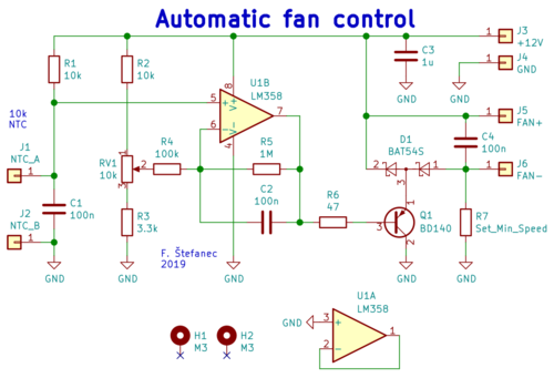
Cicuit diagram (click for full resolution)
This circuit was designed to control the fan inside my Hantek DSO5102P oscilloscope (which is also described on this website). The circuit was added after the original fan got damaged and needed to be replaced. Keeping the temperature approximately constant helped decrease DC offsets and noise.
The operating principe is fairly simple. One half of an LM358 dual op-amp is used. The non-inverting input is connected to a voltage divider consisting of the resistor R1 and an external NTC themistor (connected to J1, J2). As the temperature increases, the voltage between this input and ground decreases. This causes the voltage on the output of the op-amp to decrease too. Transistor Q1 (BD140) is operating as a voltage follower (no voltage gain, high current gain). As the voltage drop on Q1 decreases, the fan voltage increases. Resistor R7 sets the minimum speed (several tens to hundreds Ω depending on fan type). It can be omitted or replaced with a reverse biased Zener diode. The temperature is set using RV1 (a multiturn trimpot). The gain is set using resistors R4 and R5. The ratio of R5:R4 sets the gain. Higher gain leads to more "aggresive" fan control (the same change in temperature causes a higher change in fan speed). If the ratio is too high, stability problems can occur. Capacitors C1 and C2 are added to decrease effect of unwanted high-frequency signals. C3 is here for filtering/decoupling and should be placed close to U1. All capacitors are ceramic or foil type. An additional electrolytic capacitor (10 to 100 µF) can be added parallel to C3.
A single-side circuit board and a combination of SMD and THT parts was used. The KiCad project can be downloaded here.