WARNING! Risk of burns, fire or electric shock in case of improper construction and/or malfunction. If you decide to build this device, you do so at your own risk.

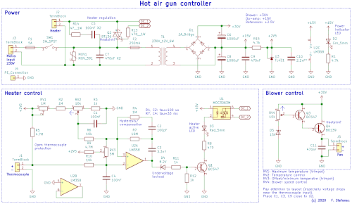
Schematic diagram (click for full resolution)
This is a simple analog hot air station using a very commonly available handle (for 858D and similar stations).
The mains input is connected to the terminal block J3. For protection, there is a 5A fuse, varistor (MOV1) and a X2-class filtering capacitor C7. The heating element is connected to J2 and is controlled using the triac Q2 (which should be placed on a heatsink, as the power dissipation can be several Watts). A snubber network is placed across the triac (R14, C5). The triac is controlled using the optotriac U1 (MOC3063M), which includes zero-cross detection (thus reducing EMI and stress on parts). The power of the heater is controlled by switching the triac on only for some half-periods. The mains input also powers a small transformer (T1, 230 V to 12 V, 6 W).
The transformer output is connected to the diode bridge D1, which forms a tapped voltage doubler together with capacitors C6 and C8. The +15V rail is used to power the LM358 op-amp (U2). C9 should be placed close to it. The +30V rail is used to power the air blower. The integrated circuit U3 (TL431) is used as a +2.5V reference. C10 should be chosen according to the charts in the datasheet for U2 so that it is stable (approx. ≤2.2 nF or ≥10 µF).
The power of the blower in the handle (it's a classic 24 V blower fan) is controlled by transistors Q3 and Q4 in a follower configuration (Q4 should be placed on a small heatsink). Air flow is regulated using the potentiometer RV4. The minimum voltage is set using the Zener diode D5. This corresponds to a voltage range of about 13.5-28 V on the output (a bit higher than the blower rating - it's possible to add a 3.9 V Zener diode between +30V and the upper end of the potentiometer).
The heater temperature is regulated by the op-amp U2A. The thermocouple is connected to J1. R5 acts as protection if the thermocouple fails open. The thermocouple voltage is compared to the voltage on the wiper of the potentiometer RV2, which sets the temperature. The maximum temperature is set using the trimpot RV1. The trimpot RV3 (and parts R6, R9, R10) compensates the op-amp offset and sets minimum temperature. RC circuits R4, C2 and R7, C3 cause hysteresis. D4 is used for undervoltage protection. Q1 is driven through it and resistors R11, R12. The transistor Q1 switches the opto-triac and indication LED D3. Due to the current, the LED is very bright, which was solved in the prototype by using a diffuser. Design of the PCB around J1 and the op-amp is fairly critical due to the very low voltages, with which the circuits work. There is no built-in temperature sensor, so the temperature will drift with ambient temperature.
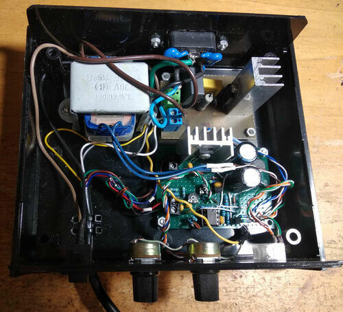
The constructed prototype works fairly well with a temperature range of 90-460°C. The control part was constructed on an universal PCB. The mains part (including the opto-triac) was constructed on a normal PCB - isolation distances are critical. The mains earth is connected to the transformer chassis, then goes to the handle (the earth wire is a bit longer, so it gets pulled out last if something happens) and also to the control circuit GND node.

Inside (click for full resolution)

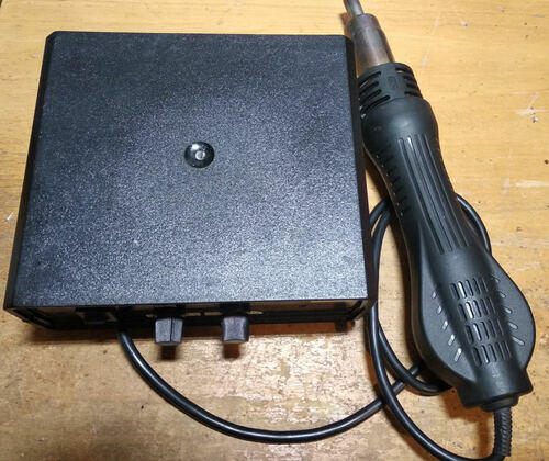
Entire device (click for full resolution)