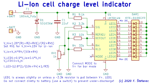
Schematic diagram (click for full resolution)
This is a simple voltage level indicator for lithium-ion cells. The heart of this circuit is the LM3914 LED driver IC. A 10-LED multi-color bargraph is used to display the charge level. I have several 18650/26650 Li-ion powered flashlights and other devices that don't have a charge level indicator - this device was designed as a tool to check the charge level quickly without having to use a multimeter.
The input is protected against accidental voltage reversal by a resettable polymer fuse (F1, 100 mA) and a Schottky diode (D1, SD103AW, some other types can be used as well - 1N5819, SS14, etc). To include overvoltage protection, a Zener diode/TVS can be used instead. The capacitor C1 is here for power bypassing/filtering - it should be placed close to U1. A 22 µF MLCC capacitor is used here (a smaller capacitor can be used,≥2.2 µF ceramic/tantalum, ≥10 µF electrolytic). The LED driver integrated circuit, U1 (LM3914N), is operating in dot mode. For bar mode, pin 9 should be connected to V+ (pin 3). The IC works by comparing the signal input voltage to 10 levels set by a voltage divider between RHI and RLO (10x 1 kΩ) and controlling corresponding LEDs. It has a built-in voltage reference, 1.28 V typical, and LED drivers with the LED current set to 10 about times the current drawn from the reference output.
The input voltage is connected to the signal input through a voltage divider (R1, R2, RV1). The trimpot RV1 should be adjusted with a voltage corresponding to an almost full charge (here 4.15 V was used) connected to the input, so that the last LED is on (I recommend setting it first in a position where LED 9 is on and then adjusting it so that LED 9 is off and LED 10 is on). A multi-turn trimpot is used here (type 3296). RHI is connected directly to REFOUT. Both the maximum and minimum charge levels are affected by RV1, R1, R2. The resistor R4 adjusts the minimum displayed charge level, it is connected between RLO and ground. Here it corresponds to about 3.3 V. To fine-adjust this lower bound, R4 can be replaced by a 10 kΩ trimpot in series with a 27 kΩ resistor. R3 (10 kΩ) loads the reference output and sets the LED brightness. REFOUT is also loaded by R4 in series with the internal divider (total 43 kΩ). The LED current is approximately 1.6 mA. All necessary formulas are included in the schematic diagram.
To display the battery level, a 10 LED four-color (red, yellow, green, blue - RRYYYGGGGB) bargraph (KYX-B10BGYR) was used. The brightness of the blue and green LEDs is quite high compared to red and yellow. This issue shouldn't be so apparent with a higher quality, better matched bargraph. A regular single color bargraph can be used as well. The LM3914 IC has some leakage on the LED1 output, to prevent the corresponding LED from always being slightly on, a 3.3 kΩ resistor can be connected in parallel to the LED. The voltage and charge level do have a significantly non-linear relationship, therefore the accuracy isn't optimal, but it is good enough for quick visualization.
The datasheet of LM3914 specifies the minimum voltage to be 3 V and proper operation with a lower input voltage isn't guaranteed. During experiments, I found the piece used here to behave somewhat erratically operation on less than about 2.5 V. This IC is no longer manufactured by Texas Instruments in the DIP package. However, equivalents from other manufactures (Gcore?) exist. I bought the IC on AliExpress for a little over 1 USD for 5 pcs, it has the National Semiconductor logo on it, but the marking looks somewhat suspicious. It works as expected, but maybe it is a remarked clone/equivalent. It is likely more economical to use a small microcontroller, however this wasn't much of a concern here when building only 1 piece. Note - when designing and building a PCB for this circuit, the traces/wires/connections should not be excessively long, especially those related to C1, U1, and the LEDs.
This circuit can be modified for other voltages as well (for more cells, Pb batteries...), by changing R1, R2, RV1 (typical voltage on SIG for all LEDs on should be 1.28 V) and R4 (to set the lower bound). However, maximum ratings of the LM3914 IC must not be exceeded (see the datasheet).
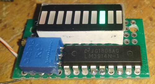
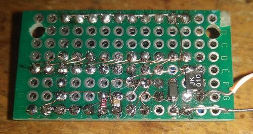
The circuit was constructed on a small piece of 2.54 mm pitch universal circuit board using a combination of SMD (mostly 0603 size) and THT parts. 0.15 mm diameter polyurethane wire was used to connect parts. Some day, it will likely be installed into a small plastic case.
Warning, many cells/batteries are capable of outputting high currents. Risk of fire if wired incorrectly. You do everything at your own risk. This circuit shouldn't also be attached to any cell/battery permanently to prevent overdischarge (which can destroy the cells).

Circuit board, top, operating (click for full resolution)

Circuit board, bottom (click for full resolution)
The board isn't cleaned yet and the 3.3 kΩ resistor in parallel to the first LED isn't installed yet in the photos.