DISCLAIMER! High voltages are present in this device, strong electromagnetic fields are emitted during operation. The high frequency high voltage output isn't likely to kill or seriously harm a healthy person, although it can cause painful burns. It's extremely dangerous to people with pacemakers or any similar devices. I refuse to take ANY responsibility for any possible injuries, legal problems, property damage or deaths, anything you find here is provided WITHOUT ANY WARRANTY and you do everything AT YOUR VERY OWN RISK!

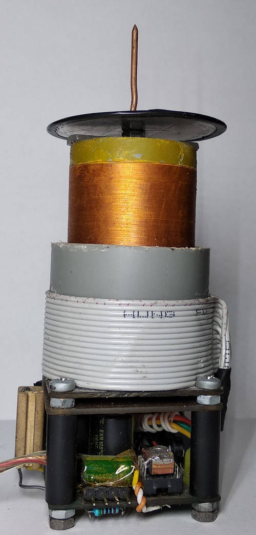
Finished device - 24 volts input (click for full resolution)
This is a very small, low voltage powered, portable Tesla coil.

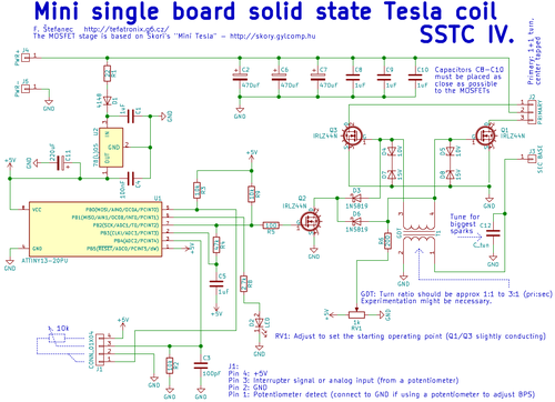
Schematic diagram (click for full resolution)
This Tesla coil is partially based on Skori's "Mini Tesla" (I used the MOSFET stage from Skori's schematic).
I used a different interrupter circuit, an ATTiny13 microcontroller is used here. The interrupter function (BPS regulation) is implemented in software. Connect a potentiometer to J1 pins 4, 3, 2 and connect pins 2 and 1 together to use it. Turning the potentiometer to zero will turn off the final stage. Min/max values are defined in the firmware. Otherwise you can supply an external interrupter signal (pin 3: input, pin 2: ground, leave the rest unconnected). The maximum duty cycle is limited to prevent destruction of the MOSFETs (shorting C5 should turn off this function). The MCU is wrapped in grounded copper foil (I had problems with interference crashing and resetting it, wrapping it in Cu foil (connected to pin 4 - GND) and adding an extra 220 µF capacitor between +5V and GND and another 100 nF one between the foil and pin 8). Firmware can be downloaded at the end of this page.
I used IRFZ44N MOSFETs in the power stage (IRLZ44N during earlier experimentation). The MOSFETs should be heatsinked. The primary has two turns (1+1, center tapped), I used a 16-wire flat cable and connected 8+8 wires in parallel (first "turn" to pins 1-2 of J2, second one between 2-3, third one to 1-2).... If the circuit fails to oscillate, change the primary leads (1, 3) and/or tune RV1. The circuit is self oscillating and uses secondary feedback.
The GDT (T1, gate drive transformer) is wound on a small ferrite core, around 20 turns, 1:1 if I recall correctly. C12 should be tuned for maximum spark length, I use two parallelled 1 nF capacitors, however the circuit will work even without C12, although not as well.
RV1 (start-up bias voltage trimpot) must be adjusted so the circuit starts correctly. Start at the lowest voltage and turn it up until the circuit starts up reliably. Setting it to a wrong position might cause the circuit to behave eratically (not starting, starting randomly, cutting out high notes if running with an external audio interrupter) or even damage the MOSFETs.
There is a piece of unetched PCB material between the coils and electronics to reduce interference.
I had some problems while trying to get this Tesla coil to behave properly. That led to physical modifications of the PCB after it was etched, therefore I will not publish the PCB design. The design isn't perfect and might require modifications.
Here is a video of the Tesla coil running.

Entire device (click for full resolution)

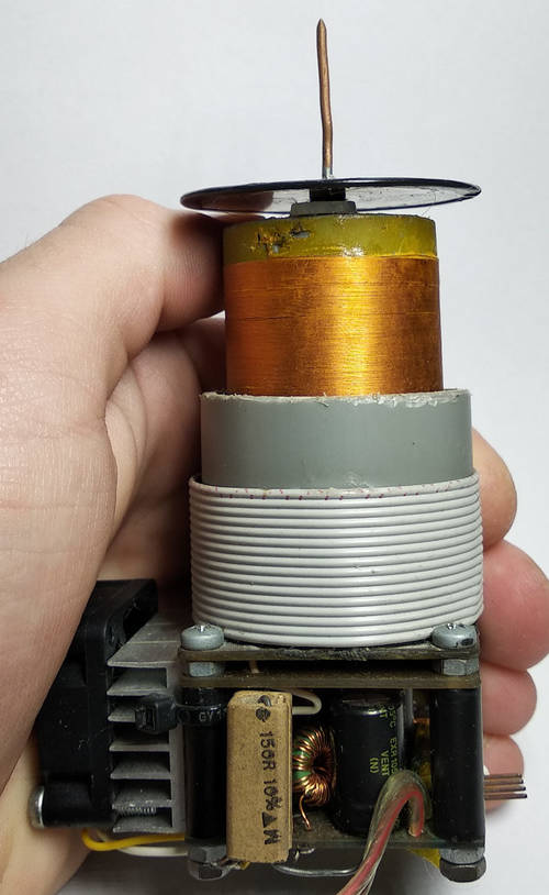
Size compared to my hand (click for full resolution)

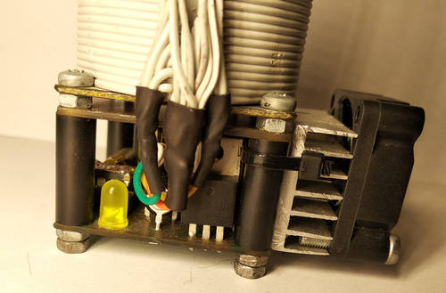
Side (click for full resolution)