This ultrasonic source is useful both as an educational tool and as a powerful animal repeller.
For education purposes, this device can be used together with a receiver and an oscilloscope or suitable voltmeter to demonstrate the propagation and attenuation of ultrasound, or to even demonstrate power transfer - a suitable receiver or another similar piezo transmitter can light up an LED attached to it (with an antiparallel diode like 1N4148) from a very short distance.
While humans can hear frequencies in the range of approximately 20 Hz to 20 kHz, many animals can hear frequencies well over 20 kHz (dogs up to approx. 45 kHz, cats up to approx. 64 kHz and mice up to approx. 91 kHz, etc. [1]).
Piezoelectric ultrasonic transmitters for sensor applications are very sensitive in a narrow frequency band, and transmitters in some standard frequency ranges (25 kHz, 40 kHz) are inexpensive, directional, and widely available. This device uses an inexpensive 16 mm, 25 kHz ultrasonic transducer as the sound emitting element.
If used as a repeller, keep in mind that just like humans, animals in general are sensitive to loud sounds, and excessive exposure to loud sound can cause hearing damage. This device should never be used at a close distance or for any longer period of time over what is absolutely necessary. It is up to the user of this device to ensure that the device is used responsibly and no harm is done to any animal or the user. Also, even though the device emits sound with frequency above the human hearing range, ultrasound still stresses the human ear and exposure should be limited, especially from a close distance. Sound pressure estimations and safe limits are described below. Fairly large voltages can be generated by the circuit due to the operating mode, especially when unloaded. You do everything at your own risk and on your own responsibility.
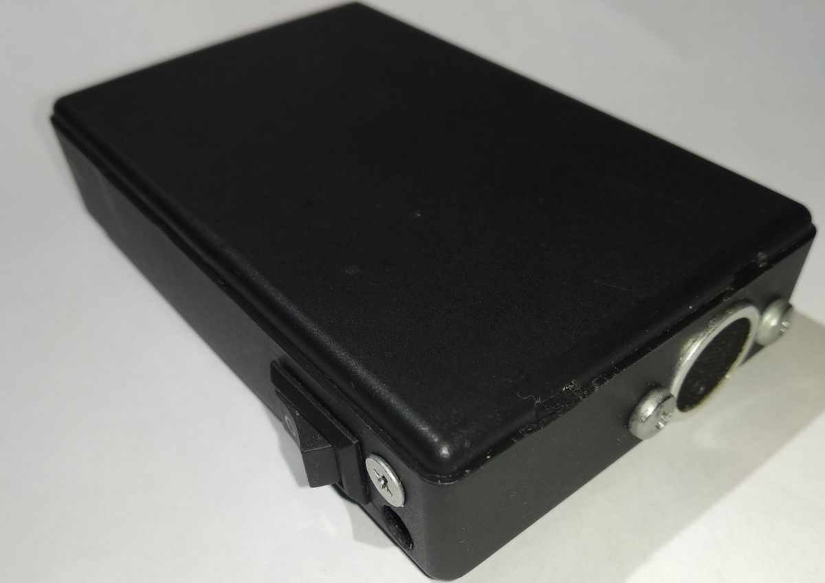
Boxed device prototype (click for full resolution)
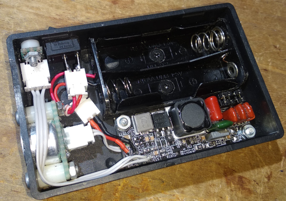
Inside the device (click for full resolution)
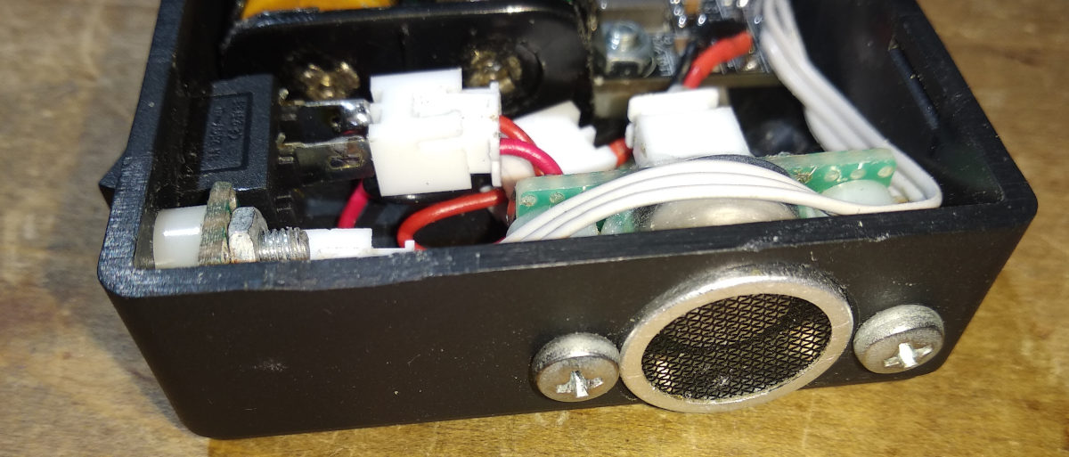
Piezoelectric transducer (click for full resolution)
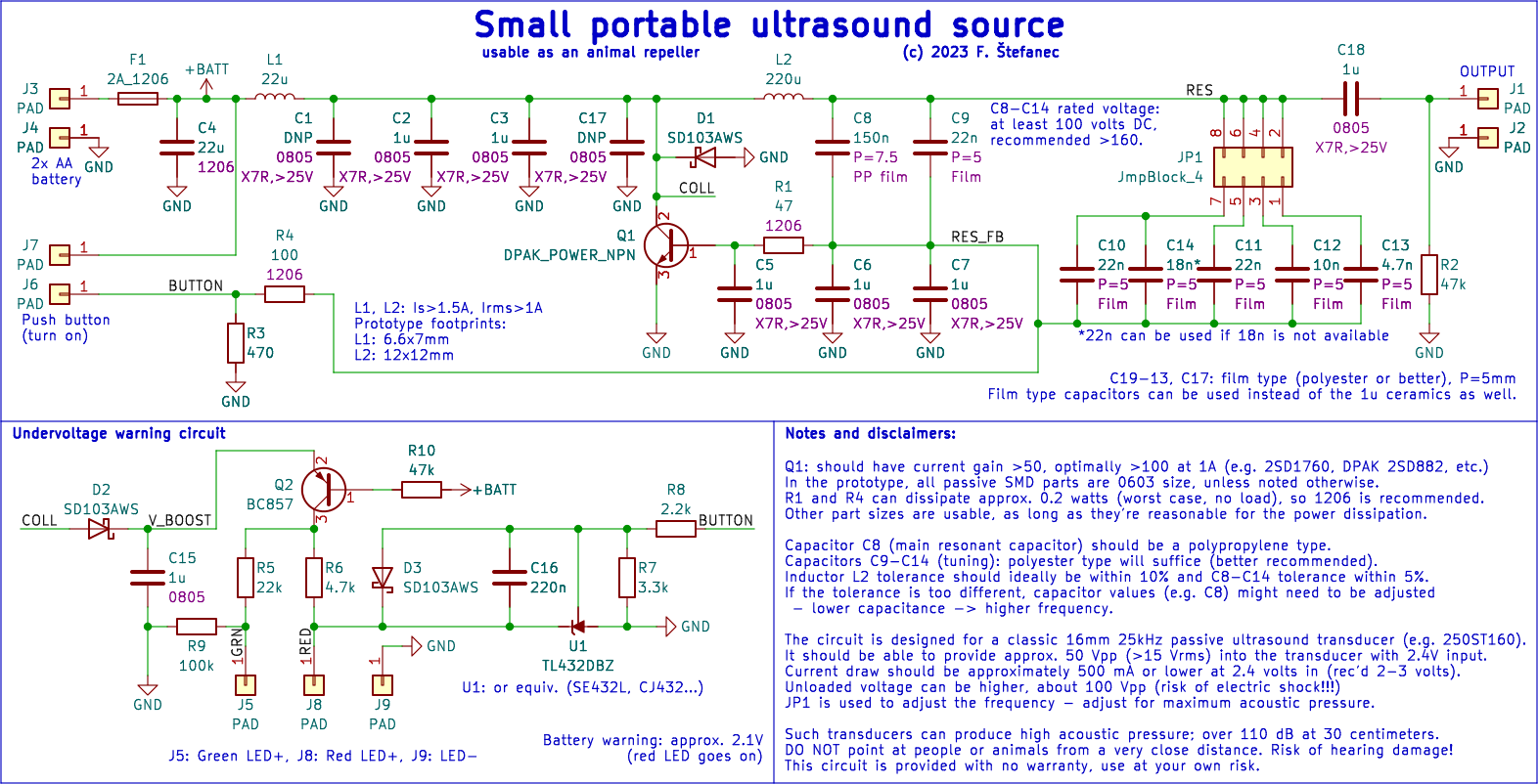
Schematic diagram (click for full resolution)
This circuit is an LC oscillator, using series resonant mode to also boost the voltage.
The power input is connected to pads J3, J4 (2 AA batteries in series) and is fused by F1. The device can be controlled (on/off) using either a button/switch connected to J6, J7 or alternatively connected in series with the batteries (then J6, J7 are just connected together - this is done in the prototype). The piezoelectric transducer is connected to J1, J2. A green LED signalizing power on can be connected to J5 (anode) and J9. A red LED signalizing low battery voltage can be connected to J8 and J9.
A filtering/decoupling capacitor (C4, 22 µF) is placed after the fuse. The oscillator itself is fed through L1, which is partially resonating with C1-C3, C17. This serves as a current source and also aids with soft switching of Q1. The node shared by those parts is also connected to the collector of the main switch transistor (Q1, the prototype uses a 2SD882P transistor, but others can be used too, as long as the gain is ≥50 or optimally ≥100 at 1 A, rated ≥3 A, ≥20 V, e.g. 2SD1760) and to the main resonant tank circuit (L2, C6-C9, tuning capacitors C10-C13). C6, C7 are placed in series with the rest of the resonant circuit and are used for sensing/feedback, also forming a voltage divider. The output to the transducer is AC coupled using C18, R2.
Feedback is taken from the tap between C6, C7 and the rest of the resonant capacitance. An additional phase shift is generated using R1 (also providing current limiting/setting bias together with R4) and C5 to ensure stable, deterministic operation. The operating frequency is hard to exactly determine, as the resonant circuits and output load, which is partially resistive and partially capacitive, affect each other, and necessary part values of the main resonant circuit for the correct frequency were tuned/determined using LTspice simulations. The same was done with the first circuit to achieve soft switching. Then adjustment of the second circuit was repeated. Very roughly, before manually tuning the values/stepping and tuning parameters, the second resonant circuit values were set so that $f_{OP} \approx 1/(2 \cdot \pi \cdot \sqrt{(L \cdot C)})$; $\sqrt{(L \cdot C)} \lt k \cdot R_{LOAD,SER}$ (k being about 10-20, and assuming that at resonance, the transducer behaves like a RC circuit, with a series model having an impedance of several hundred Ohms, with the real and imaginary parts being similar). The initial inductance and capacitance for the first resonant circuit were chosen 10 times lower (L) and 10 times higher (C), respectively. Some care must be taken when designing the circuit layout (keeping short distances especially for the main current loops). The exact operating frequency can be adjusted using the jumper block JP1, by installing jumpers on positions 1-2 (slight decrease), 3-4, 5-6, 7-8 (major decrease), or any combination, in a range of about ±2 kHz around the center of 25 kHz (approximately, with only 1-2 or only 3-4, 5-6, 7-8 set).
Power for the LED signalization circuit is taken from the Q1 collector through D1 and filtered using C15 (peaks are about 3 times higher than the supply voltage, enough to power a blue-green LED and keep more constant brightness overall). Q2 turns on the LEDs if the circuit is oscillating and the node V_BOOST is about 0.7 volts above +BATT (button must be pressed or bypassed), otherwise they're off to conserve the battery. R5 limits current for the green LED and R9 increases its minimum voltage, and also decreases current a bit. Current for the red LED is limited by R6. The red LED is bypassed by U1 (voltage reference - TL432, CJ432, SE432L or equivalent) if the battery voltage (on the BUTTON node) is above $V_{REF} \cdot (R7 + R8) / R7$, so for 1.25 volts, 3.3 kΩ, 2.2 kΩ, approx. 2.08 V. Above this battery voltage, the red LED is off. C16 is added for stability and D3 to prevent voltage across U1 from dropping too much, which causes some problems (big hysteresis) with some clones.
At 2.4 volts input.
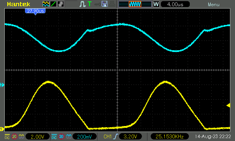
Waveforms (yellow: Q1 collector-emitter, blue: base-emitter) (click for full resolution)
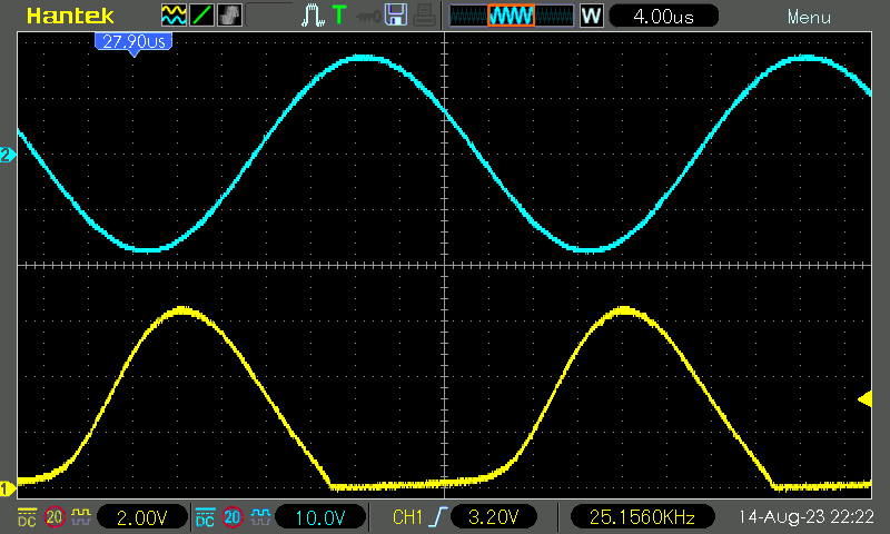
Waveforms (Y: collector-emitter, B: piezo output) (click for full resolution)
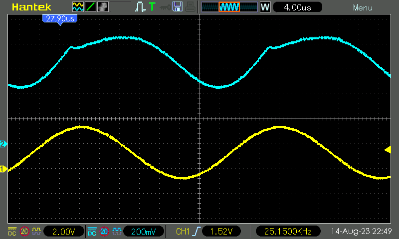
Waveforms (Y: voltage on C6+C7, B: base-emitter) (click for full resolution)
To estimate the sound pressure at a certain distance lREAL and voltage VREAL, inverse square law will be used, given that reference values are given for some reference voltage and distance. If power drops with the square of the distance ratio and rises with the square of the voltage ratio, and we know the reference values, the acoustic intensity can be estimated as:
$L \mathrm{[dB]}$ = $L_{REF} + 10 \cdot \mathrm{lg}(\dfrac{P_{REAL}}{P_{REF}})$ = $L_{REF} + 20 \cdot \mathrm{lg}(\dfrac{V_{REAL} \cdot l_{REF}}{V_{REF} \cdot l_{REAL}})$
ProWave 250ST160, a transducer very similar to the one used here, has a specified sound pressure of 112 dB (0 dB reference: 20 µPa) at 10 volts RMS and 30 cm. Taking the measured peak-peak voltage of 36 VP-P with a near-sinusoidal shape, the RMS voltage is $V_{RMS} = 0.5 \cdot \sqrt{0.5} \cdot V_{P-P}$: 12.7 V.
Plugging this into the equation above, the estimated sound pressure is 103.6 dB at 1 m, 97.6 dB at 2 m and 89.6 dB at 5 m.
For humans, NIOSH specifies a maximum recommended exposure level to 85 dBA (dBA: weighted according to the A-curve for human ear sensitivity) over an 8-hour workday. This will be used in the calculations. EU-OSHA specifies a limiting value of 87 dB for the same time (values relevant and found at the time of writing this article). This halves with every 3 dB increase. For a human, if this sound was audible and at the unit sensitivity after weighting, theoretically, the maximum safe time at 1 meter would be (according to $\textrm{8 hours} \cdot 10^{((85-L)/10)}$) approximately 6.6 minutes at 1 meter in the absence of exposure to other loud sounds. Putting the values for 2 and 5 meters gives 26 and 166 minutes, respectively. The sound is not audible to humans, so this can not be exactly applied, and the limiting time is probably much higher, but for safety reasons, I recommend limiting exposure to the output to an absolute minimum. Taking the curves from [1] for dog hearing ranges, the sensitivity is approximately 10 dB lower at 25 kHz compared to the peak. Still, precautions and an ample reserve should be taken, and if the device is used as a repeller, it should be used only for a very short time, from a reasonable distance.
ZIP archive: KiCad 7 project, exported Gerber files, LTspice files, PDF schematic, manual placement illustration - hardware design license is Creative Commons BY-SA 3.0, or newer (4.0), or 3-Clause BSD.
[1] https://www.lsu.edu/deafness/HearingRange.html