WARNING! This circuit works with lethal voltages and produces a strong electric field. If you decide to build it, you do so at your own risk (I take no responsibility for any consequences).
This is a small vacuum tube Tesla coil powered from mains through a voltage doubler. It's based on the PL504 or PL500 vacuum tube.

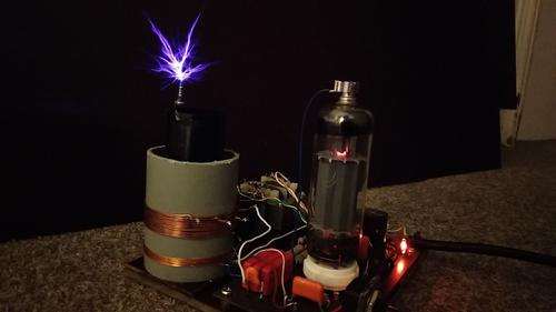
Finished device, operating (click for full resolution)

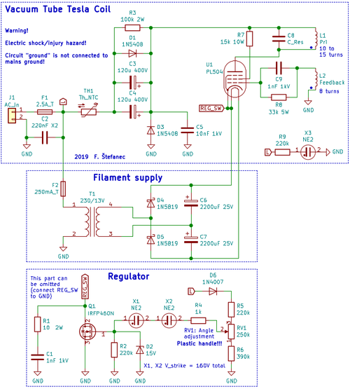
Schematic diagram (click for full resolution)
The schematic diagram is split into three parts. Warning - circuit "ground" is NOT connected to mains ground and must be left floating! The upper part consists of a fuse (F1), filtering capacitor C2, inrush limiting NTC thermistor TH1 (a thermistor with ~5 Ω resistance at room temperature taken from an old PC supply is used here), voltage doubler (C3, C4, D2, D1, D2), capacitor C5 (filtering/RF bypass), the VTTC circuit itself (U1, R5, C8, C9, R8) and signalization (R10, neon glow lamp X3). The mains input is connected to J1 and is protected by the fuse F1 (2,5 A, slow type). A single capacitor (around 150-330 µF) can be used instead of C3+C4. The double capacitors are protected against reverse polarity using the diode D1 and discharged by R3 (the time constant τ is 24 s and the capacitors are discharged to a safe voltage within 1 minute). Both D1 and D2 are type 1N5408, rated for 3 A forward current and 1000 V reverse voltage.
The VTTC itself is wired as a Class C oscillator (Meissner/Armstrong circuit). Feedback is connected to the first (control) grid of the vacuum tube through C9 and R8. The second grid is connected to the power rail through R7 (I used two 33 kΩ/5 W resistors in parallel to get 16,5 kΩ/10 W).
The anode of the vacuum tube is connected to the primary resonant circuit consisting of L1 (primary coil) and capacitor C8. Both L1 and L2 are wound on a 5 cm diameter PP pipe. L1 has 15 turns with several taps between turns 10 and 15. L2 has about 8 turns. C8 is built from three WIMA FKP1 1 nF/2 kV= capacitors in series (333 pF, 6 kV). Another 33 pF 3 kV capacitor is connected in parallel, giving a total capacitance around 370 pF. The resonant capacitor must be able to withstand high voltages (I recommend >2 kV) and high current (it's a good idea to use pulsed use rated capacitors such as FKP1). The correct capacitance and inductance depend on the secondary resonant frequency (should be tuned to the same frequency), fres=1/(2*π*sqrt(L*C)). The cathode node is labeled REG_SW. If regulation isn't implemented, it should be connected to GND
Beginnings (or ends - but it must be the same on both windings) of L1, L2 are labelled with a dot. The circuit won't work with incorrect phasing.
The second part is powering the filament. I used a 13 V transformer with a doubler (measured voltage 26-28 V with load). A 27 V, 0.3 A transformer can be used instead (with no doubler - preferred). The transformer is protected by the fuse F2.
The third pard is omittable. It's designed to regulate power (switch the circuit by connecting the cathode to GND). The on-time for each mains cycle is set using RV1. A weaker (lower voltage and current) MOSFET can probably be used in place of Q1 (IRFP460N), which is a bit overkill. The MOSFET gate is discharged by R1 and protected by D2. The mains voltage is half-wave rectified by D1. R5, R6, RV1 form an adjustable divider. If the voltage on the output of this divider gets high enough, neon lamps X1, X2 (strike voltage around 80 V per lamp) will turn on and their voltage drop will decrease, turning on Q1. If the voltage on the divider output drops, the lamps will turn off and Q1 will also turn off. This limits the duty cycle to around 5-40%, decreasing heating.
The secondary coil has a diameter of around 3.2 cm, is ~8 cm tall and resonates at around 2.4 MHz. It was wound with enameled wire (~0.15 mm). The PCB was drawn by hand with an etch-resistant marker.
In this case, the tube I used (PL500) was already quite worn, with a better or less used tube, the sparks will probably be larger. The circuit works.

VTTC (click for full resolution)