DISCLAIMER! High voltages are present in this device, strong electromagnetic fields are emitted during operation. The device should NEVER be run without proper shielding. I refuse to take ANY responsibility for any possible injuries, legal problems, property damage or deaths, anything you find here is provided WITHOUT ANY WARRANTY, you do everything AT YOUR VERY OWN RISK!
This is an upgraded version of this Tesla coil (SSTC II). The bipolar transistor (BD139) was replaced with a MOSFET (IRF510). This MOSFET was chosen because of its good availability, low gate capacitance and fairly high speed.

Circuit diagram (click for full resolution)
The input voltage is connected to the connector P1. The primary coil is connected to P3, the secondary base is connected to P2.
The parts R1, C1, D1, RV1 form a start-up circuit. A small voltage is connected to the MOSFET gate - this causes the MOSFET to partially open. Transient effects and noise will cause the circuit to start oscillating. The start-up voltage has to be high enough for the circuit to start oscillating but low enough to prevent overheating/damaging the MOSFET. Set RV1 to zero before the first start and then gradually turn it up. It's a good idea to use a current limited power supply for the first start (or any debugging) - around 12 V, 500 mA
The gate voltage is clamped to approximately ±16 V by D2-D5.
The output stage operates similar to class E. The capacitance of C3 should be tuned for minimal losses/soft switching (or for maximum spark length). I don't have any capacitor in place (the drain-source capacitance seems to just about enough). In other cases, it might be necessary to put a small capacitor in place (several 10s of picofarads). The inductance of L1 (RFC) is not critical, but should be much (at least 10 times) higher than the primary inductance.
The secondary coil dimensions are 1 by 2.5 centimeters, wire thickness: 0.1 mm, ˜250 turns. The primary coil is wound around its bottom end.
Discharges at such high frequencies (> approximately 5 MHz) resemble a flame.
This version needs much better cooling than the previous one. The efficiency isn't probably much higher and the power input is considerably increased. It runs fairly at around 12-14 volts on the input. Sometimes the spark/arc has to be initiated manually.
To reduce the average power (and thus the heating), an interrupter could be used.

PCB underside - the PCB is populated with both SMD and THT parts (click for full resolution)

Neon lamps (click for full resolution)

Heatsink (click for full resolution)

Fluorescent lamp and big neon lamps (click for full resolution)
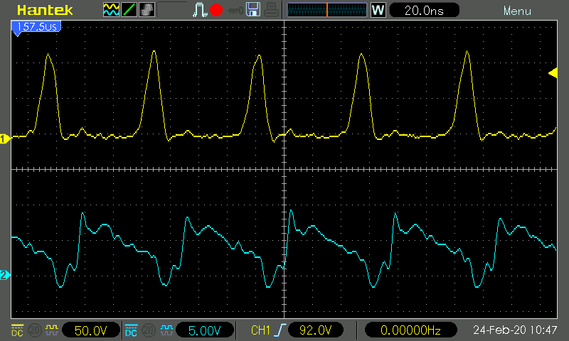
Waveforms (top: drain, bottom: gate) (click for full resolution)
