DISCLAIMER! This device shouldn't cause any considerable interference, but it still works with high frequency alternating magnetic fields. Build and use at your own risk. Voltages present in the device can be several times higher than the input voltage.

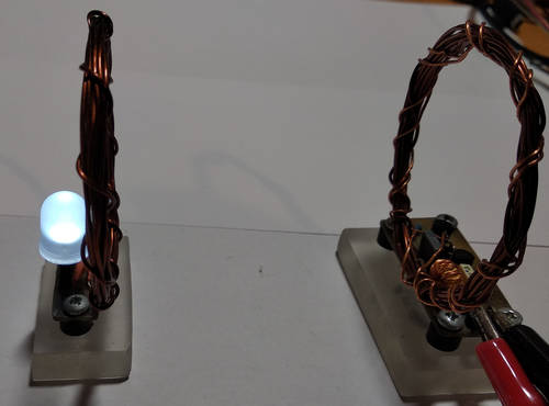
Finished device (transmitter+receiver) (click for full resolution)

Transmitter schematic diagram (click for full resolution)
The transmitter is basically a regular resonant Royer oscillator consisting of very few parts. There are two transistors (Q1, Q2 - BC337-25), the primary and feedback coils (air cored, 10 turns center tapped - 5+5 turns primary, 2 turns feedback, wound with ~0.5 mm enameled wire on 5 cm dia). Then there's C1, the capacitor that forms a resonant circuit together with the primary coil, which resonates at around 1 MHz. The resistor R1 provides current into the bases of the two transistors (Q1, Q2). L3 is a 50 µH inductor (not critical, anything around 33 to 100µH is probably fine). Capacitors C2 and C3 are used for filtering.
This circuit, meanwhile being very simple, has some downsides. Connecting the coils in a wrong way (e.g. feedback winding not connected or connected the wrong way) will most likely lead to destruction of at least one of the transistors (Q1, Q2). It's MANDATORY to keep winding direction/coil polarity the right way. Voltage on the resonant circuit (L1, C1) can be around 3-4 times higher than the input voltage, this is normal but it's good to keep it in mind, as the voltage can get quite high (approx. 40 V with 12 V in - pushing the transistors to their limits). C1 should be of good quality (film capacitor).
It's a good idea to put a 100 mA resettable fuse (PolySwitch, etc...) in series with the power input for safety.

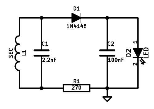
Receiver schematic diagram (click for full resolution)
The coil should be the same as in the transmitter, e.g. 10 turns on 5 cm diameter, center tapping is not necessary here. The capacitor (C1) that forms the resonant circuit should be the same too (2.2 nF 100 V). R1 should be rated for a reasonable power dissipation (maybe around 1-2 W or so, but must have low inductance, no wire-wound resistors) if the receiver is going to be very close to the transmitter while operating at >6 V. It might be a good idea to increase the value to around 470 Ω-1 kΩ. I have a regular 270 Ω carbon resistor in place, but can't recommend that for anything else than low power operation (e.g. 4 V or 5 V into the transmitter). A 470 Ω, 1 W resistor is a better choice. The diode (D1) should be fast and have low capacitance.
This circuit works well enough for demonstration purposes. There is still some room for improvement though. A more efficient receiver (in case the load is going to be anything more demanding than a small LED), or at least a better regulated one, would be much better. As seen in the image above, I have the receiver & transmitter mounted on small pieces of plexiglass, which is OK, but some mechanical support for the coils might be useful.