This circuit works with dangerous voltages. I don't take any responsibility for any direct or indirect consequences (legal issues, property damage, injuries, deaths...) of building and using this device. You do so at your own risk.
This is a very simple flyback transformer driver. This circuit can be found on the net in many variations.
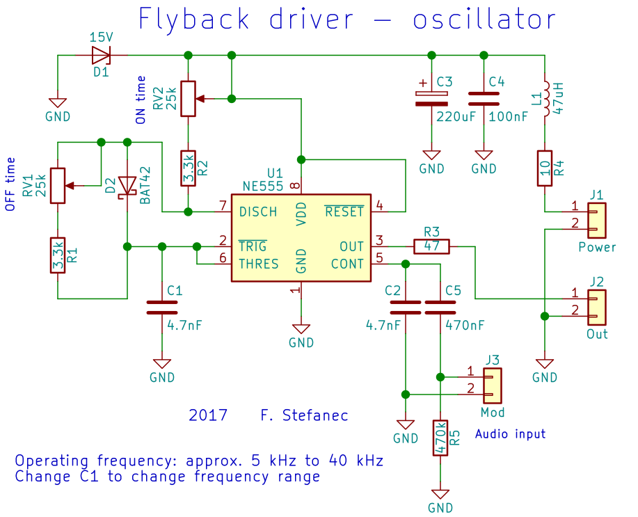
Oscillator schematic (click for full resolution)

MOSFET connection diagram (click for full resolution)
This circuit is fairly simple. It's powered from a 12 volt supply. Parts L1, R4, C3, C4, D1 on the oscillator board take care of voltage filtering/spike suppression. The main IC (NE555) is used in astable mode here. D2 (the diode between pins 7 and 6) allows to set a duty cycle under 50%. Trimpots RV1 and RV2 set the frequency and duty cycle (RV2 sets the on time, RV2 sets the off time). The timing capacitor (C1, 4.7 nF) sets the operating frequency (together with RV2, RV1, R1, R2). The range is approximately 5 to 40 kHz. There's a 47 Ω resistor in series to the output (MOSFET gate). I used a short piece of twisted pair between this board and the power MOSFET. This twisted pair also forms a few turns around a tiny ferrite core.
The power MOSFET directly drives the primary coil (I used approx. 7 turns wound on the exposed part of the core). Capacitors C1 and C2 in the second circuit diagram should have decent quality and should be placed close to the MOSFET. The MOSFET heats up a lot and has to be properly heatsinked! It also has to be "avalanche rated" and has to have adequate voltage and current ratings - it has to "eat up" voltage spikes from the primary coil. Adding a proper RC circuit between the drain and source wouldn't do any harm.
There's an input (J3) on the oscillator board for audio modulation possibilities. Most audio sources don't have enough amplitude for good sound quality/loudness, so it's needed to use a small preamplifier. A trivial single transistor amplifier will work (this one for example, you can experiment with the part values - it's far from ideal, just a quick experiment):

Preamplifier circuit (click for full resolution)
HERE is a video showing audio modulation.
This circuit isn't ideal (the 555 IC doesn't have a very high output current resulting in longer-than-ideal rise/fall times...), but it's good enough for basic tests and experiments. After modifications it could be used to drive ignition coils as well.
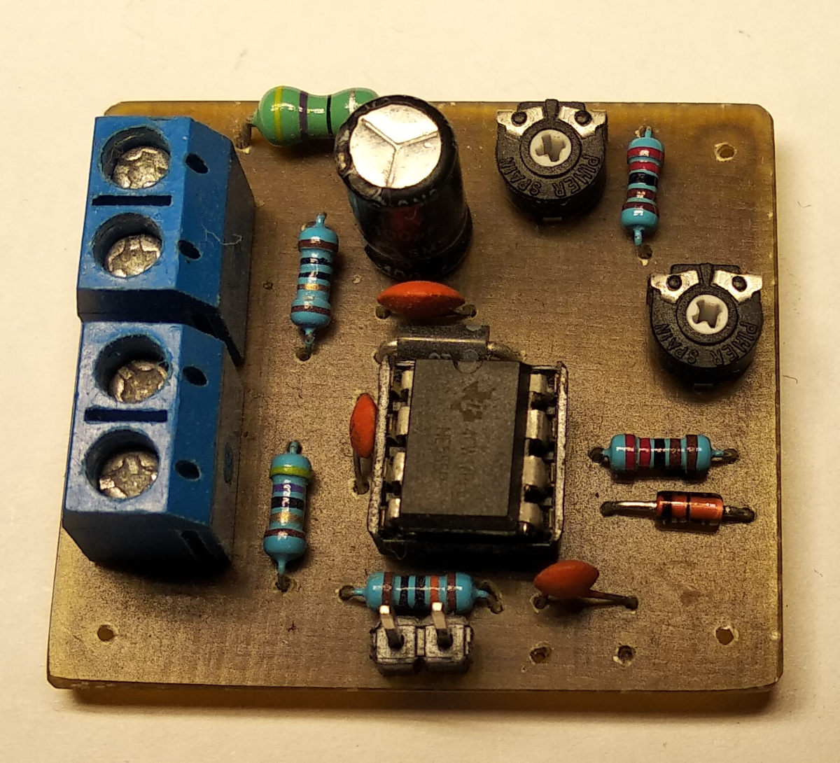
Oscillator circuit board (click for full resolution)

Arc (click for full resolution)
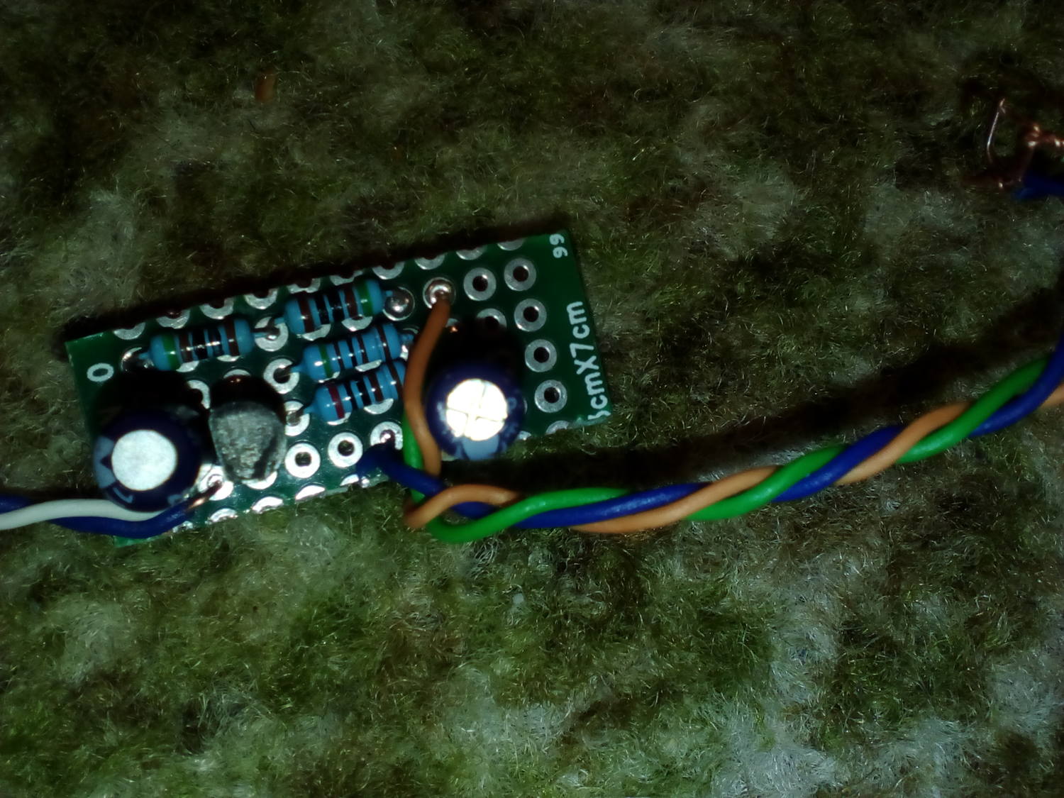
Preamp (on a piece of protoboard) (click for full resolution)
KiCad files for the oscillator board can be downloaded HERE.