DISCLAIMER! UV-C radiation is dangerous, risk of eye damage, skin damage or other injuries. UV-C radiation is ionizing and damaging to all forms of life. Even short eye exposure may cause painful inflammation. You do everything at your own risk.

Operating (click for full resolution)

Schematic diagram (click for full resolution)
This DC-DC converter is designed to drive 3 watt 0.3 A "incandescent lamp style" UV-C lamps, which are commonly sold for disinfection/air purifying purposes. The filament is partially coated with emissive material. As soon as it heats up, the lamp starts acting more like a glow discharge lamp, emitting both visible and UV-C radiation due to mercury content inside the lamp, and the voltage across the lamp drops.
The DC-DC converter is based on the MT3608 integrated circuit, which is a step-up converter IC with an integrated MOSFET in a 6-pin SOT-23 package. This IC is not designed to be used in constant current mode, but its 0.6 V reference voltage is low enough to be used as a current sense reference at the cost of some reasonable efficiency loss. The voltage drop on the current sense resistor R3 is controlled by the voltage reference. The lamp current can be calculated simply: $I_{lamp}=0.6/R_3$. Voltage feedback is implemented using parts R1, R2 and D2 (16 V Zener diode). This feedback circuit structure is not mentioned in the datasheet and could cause issues with the IC's integrated loop compensation circuitry, thus leading to instability and oscillations, however it was found that using somewhat lossy capacitors makes the feedback loop stable - C3 and C4 are electrolytic capacitors, C1 and C2 are ceramic capacitors, which must be placed right next to the IC and current loop sizes must be minimized. Raising their value to 10 µF seems not to affect stability, but increases efficiency by reducing the losses due to the ESR of C3. In the prototype, a 6.8 µH inductor was used instead of 22 µH. It must be able to handle the MT3608's maximum switch current (4 A) without saturating. Estimated efficiency is ≥80 %.
This circuit does not include any under-voltage (or other) protection that is necessary when used together with a Li-Ion battery, such protection circuitry must be connected externally. With such addititonal protection and a 18650 cell (or similar), this device might be used as a portable Li-ion powered disinfection device.
These lamps are probably not designed to run on DC current and thus might degrade quicker, but this wasn't tested as this device was used only briefly.
Video of the lamp starting on this DC-DC converter, running from 3.7 volts.
KiCad files - single-side board design. At ≥1 MHz, PCB layout is already fairly critical, I recommend using a double-side PCB.
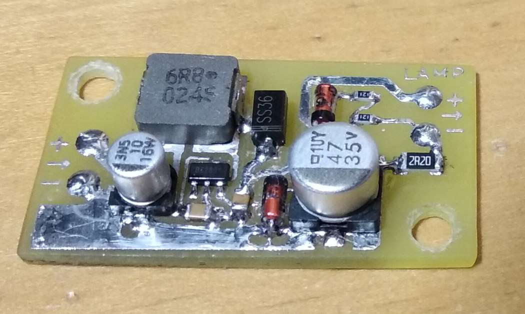
Circuit board (click for full resolution)